
Summary
The RC Baja has many vital parts of it that make it useful for what it does. For example, if the hubs are not made from a strong material they might deform upon high torque and lose a wheel. The overall objective for this project is to have the RC hold up over the entire course without failing. Ryders part in this is to analyze the differential and drive train. For example, analysis will be done to calculate torque in all parts of the system to ensure the material chosen can withstand the load. This section will state the requirements and provide green sheet drawings of all components Ryder is responsible for.
Requirements
Differential:
§ Gears inside differential must be able to spin at a 3000-rpm difference
§ Should not surpass temperatures of 50 degrees C from friction
§ Must be made in parallel to the guidelines provided. Must be designed by the team.
Differential Housing:
§ Able to withstand friction from rubbing up to 10500 rpm where gear rod touches the cover from the inside of housing
§ Should not be larger than 2 inches in diameter with outside gear attached
§ Cannot be purchased at an RC shop
Transmission/Internal Gears:
§ Must have no more than 2 gears inside the actual box.
§ Gears will be smaller than differential gear
§ Can be but is not pertinent that it is comprised from toy sets
Transmission Cover:
§ Needs to be able to double as a motor mount
§ Dustproof
§ Needs to be made from erector or alike set
Calculated Analysis

Pinon/Spurt gear Torque:
It was decided that the spur gear be plastic so if anything happened to a gear, the plastic gear would shear first since its inexpensive and easy to access. Gear analysis was done on the two gears to determine that the gear needed to either be Kevlar or actual steel to withstand the torque the motor could produce. Luckily most of the tests do not yield a 'full throttle' environment so a simple blend of polymers and ABS casted was found to have similar properties.
Differential Cover Material:
The differential cover was already planned to be printed using PLA, but analysis still needed to be done to determine whether or not it would be able to handle the kind of heat the car produces regularly. After finding a table that had a range of what the allowable heat ranges were for certain materials, it was determined that ABS or PLA would work since the internal temperature of the car should not exceed 80 degrees C with proper lubrication.


Pin Required Diameter:
There are two gears that have shafts coming out from either side of the differential and in order to index the drive shafts onto them, a pin or set screw was needed. After calculation it was found that a 2mm pin would be sufficient if it was the steel material selected.
Batterie Size:
A simple calculation was done to see what type of batterie would produce what output from the chosen motor. Since the maximum output rpm from the motor was rated at 100,000rpm and the largest allowed batterie size was a 2 cell Li-Po; it was found that the batterie chosen would only reach 2/3 of the potential the motor had to offer.


Tire Dimeter:
A larger tire will travel a farther distance in less rotation than a smaller one. Using the speed the car is supposed to reach from the requirements, it was determined that both of the wheel selections available would be sufficient since the motor spins at such a high rpm.
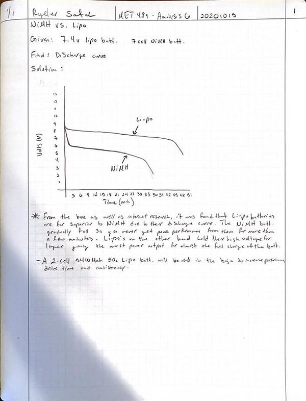
Batterie Discharge Curve:
A trial was done to see which batterie would hold their charge the longest and provide the highest power output. After hooking both batteries up to the motor at full speed for increments of 3 minutes, the voltage was checked with a volt meter and the Li-Po batterie was found to have the higher power for a longer duration. A 2-cell 5400Mah Li-Po batterie will be used due to ROAR specifications.

Shaft Angle:
Knowing the shaft length and also being able to extend or compress the drive shafts at all times, a starting angle was needed to know far out to mount them on the a-arms. Finding the total length using Pythagoreans theorem, an angle was able to be calculated out to be 9.83 degrees as the resting angle the drive shafts would sit at.
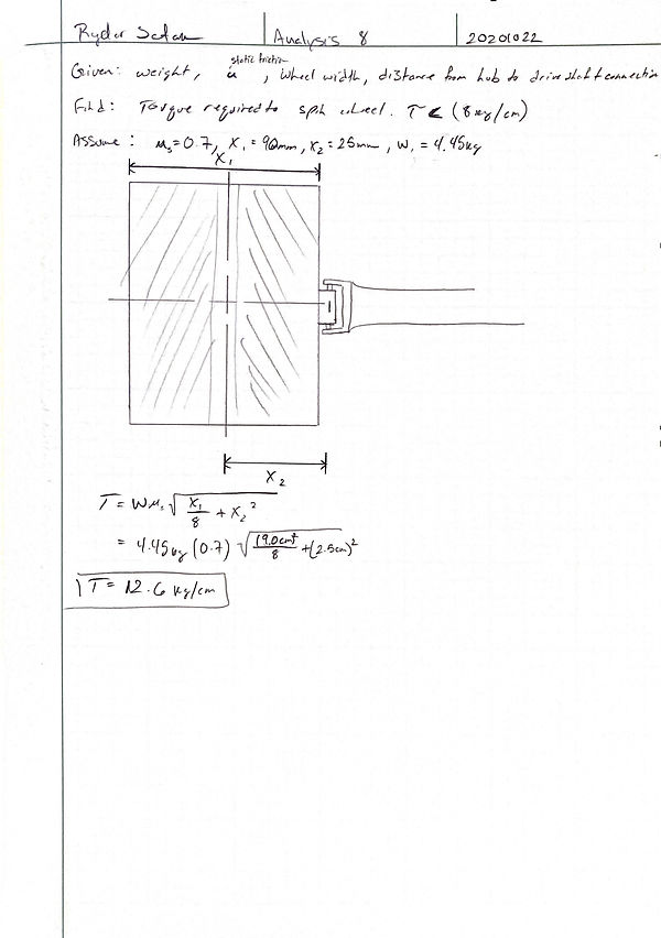
Torque Required to Spin Wheel:
After discussion, the larger wheel diameter was chosen and with a simple torque calculation using an average friction coefficient, it would take around 70lb/in (to scale) of torque to move the wheel.
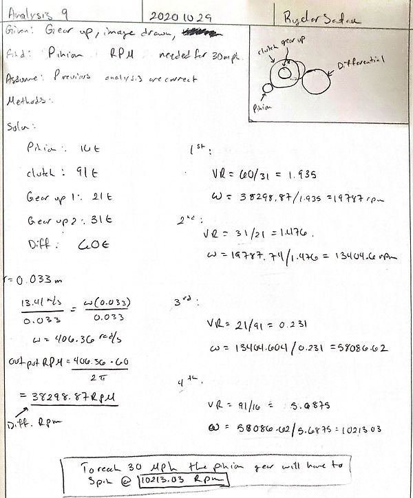
Gear Up:
There are 3 internal gears in the gear box as well as two external including the differential and the pinion on the motor. A gear train analysis was done to see both how fast the differential would be spinning to reach the required speed and then how fast the pinion would need to spin as well. The pinon would need to spin at just over 10K rpm's which would cause the differential spin at 38K rpm.
Wheel Hub:
After choosing the pin for the drive shaft, a pin was needed to index the hex hub as well so why no the same pin since the index was the same size diameter. After a small torque calculation the torque was in fact going to be much less than the pin would ever bend at even thought it was almost twice the torque the other application is experiencing.


Motor Choice:
The team already had the motor of choice so a Hp calculation was done as well as a pitch line speed analysis. This was done purely out of curiosity just to see how many horse power to scale the car was outputting and how this would effect the average velocity. The average velocity using the average horse power came out to be 5.35m/s. This is what the motor could sustain for a very long period of time.
Gear analysis:
Stress analysis on the gears was necessary to determine if the gear material chosen would be suitable. Using the output Hp from previous calculation as well as the pressure angle from the gears, the normal force ended up being the greatest yet still no where near enough force to fail a gear due to shear force.
