top of page

Methods and Construction
This project was designed, manufactured and tested in the city of Ellensburg, while using the resources and workshops on Central Washington University’s campus. Major components were created manufactured onsite while other components were acquired from outside retailers. All were completed within the restraints of Central’s Hogue building as well as the ASME RC Baja Car Contest Rules. The use of engineering design programs such as SolidWorks, Autodesk Inventor, MDSolids, and other various programs were used to aid in the design and manufacturing of this RC Baja Car. The use of these programs helped visually conceptualize the design which made the creation of this project much easier.
It was concluded that for the smaller parts of the project those would be purchased from outside retailers for the difficulty they would provide in trying to manufacture. Big components like the Chassis, A-arms, Shock towers and Main Gear locker would be manufactured as those would prove to be less difficult in manufacturing. Items such as the motor, screws, bolts, or any smaller parts required to go on the chassis will be purchased from an outside retailer. The decision of a wooden chassis was decided as the team wanted to try something different from previous years and concluded that by using a wooden frame it would reduce the weight of the car as a whole instead of using a form of metal. The chassis is designed so that the front and rear are almost identical so that in the case one end fails it can be easily fixed by rotating some parts. The chassis is to be made of wood on a CNC machine, for the ease of use and intricacy of our design. The CNC was also chosen as the manufacturing process because the chassis is less likely to be produced with any flaws because the machine is less likely to create errors that humans would make. The A-arms and the A-arm pins would be 3D printed as decided by the team. This decision was made as the team realized that 3D printing these components would be cost efficient and time efficient as well because they are custom designed parts that have intricate designs. The location of the chassis where the A-arms would attach would be made with a clearance fit of RC2 because the pin holding it needs to be tight but not too loose so that the A-arms stay connected to the chassis. This RC2 clearance fit is needed so that the A-arms can still move freely from the A-arm pins but not too much as to where they would fall off.
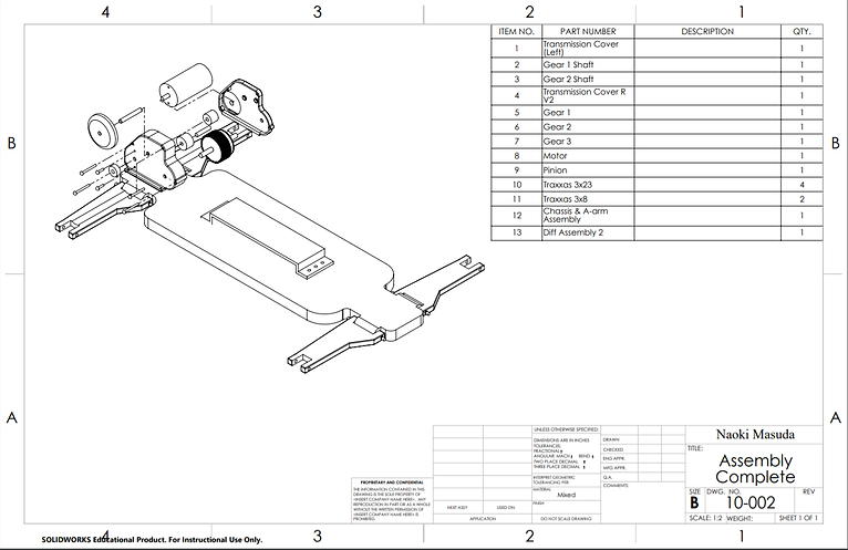
Complete Assembly

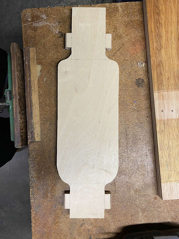
Drafted chassis on wood
Cut out chassis
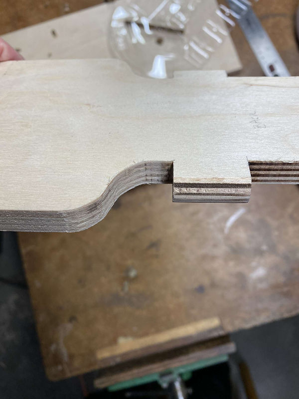
A-arm pin cutout location
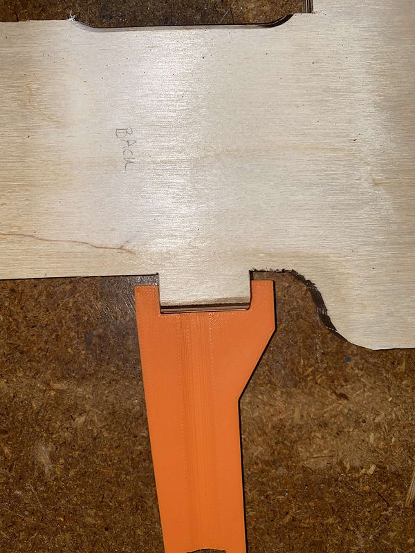
A-arm attachment at location

Front and rear A-arms

Completed chassis

Completed chassis

Chassis construction

Complete Assembly
bottom of page